|
|
|||
MOTORI AC
|
|||
|
|||
|
|
|||
|
INTRODUZIONE
I
motori a induzione AC sono i motori più comuni utilizzati nei sistemi di
controllo del movimento industriale, così come negli elettrodomestici
alimentati dalla rete principale. DDesign semplice e robusto, basso costo,
manutenzione ridotta e collegamento diretto a una fonte di alimentazione AC
sono i principali vantaggi dei motori a induzione AC. COSTRUZIONE DI BASE E PRINCIPIO DI FUNZIONAMENTO
Come la maggior parte dei motori, un motore a induzione AC
ha una parte esterna fissa, chiamata statore e un rotore che ruota all'interno
con un divario d'aria accuratamente ingegnerizzato tra i due. Praticamente tutti i motori elettrici utilizzano la
rotazione del campo magnetico per far girare i loro rotori. Un motore a
induzione AC trifase è l'unico tipo in cui il campo magnetico rotante è creato
naturalmente nello statore a causa della natura dell'alimentazione. I motori DC
dipendono o dalla commutazione meccanica o elettronica per creare campi
magnetici rotanti. Un motore a induzione AC monofase dipende da componenti
elettrici aggiuntivi per produrre questo campo magnetico rotante. STATORE Lo statore è composto da diverse lamine sottili di alluminio
o ghisa. Sono forate e serrate insieme per formare un cilindro cavo (nucleo
dello statore) con delle scanalature come mostrato nella Figura 1. Bobine di
fili isolati sono inserite in queste scanalature. Ogni raggruppamento di
bobine, insieme al nucleo che circonda, forma un elettromagnete (una coppia di
poli) all'applicazione dell'alimentazione AC. Il numero di poli di un motore a
induzione AC dipende dal collegamento interno degli avvolgimenti dello statore.
Gli avvolgimenti dello statore sono collegati direttamente alla fonte di alimentazione.
Internamente sono collegati in modo tale che, applicando l'alimentazione AC, si
crea un campo magnetico rotante.
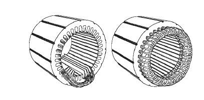 FIGURE 1: A TYPICAL STATOR
|
|
||
|
|
|||
|
|
|||
|
|
|||