|
|
|||
MOTORI AC - 2
|
|||
|
|||
|
|
|||
|
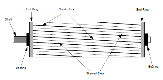
ROTORE
Il rotore è composto da diverse
lamine sottili di acciaio con barre equidistanti, che sono fatte di alluminio o
rame, lungo la periferia. Nel tipo di rotore più popolare (rotore a gabbia di
scoiattolo), queste barre sono collegate meccanicamente ed elettricamente alle
estremità tramite l'uso di anelli. Quasi il 90% dei motori a induzione ha rotor
a gabbia di scoiattolo. Questo perché il rotore a gabbia di scoiattolo ha una
costruzione semplice e robusta. Il rotore è costituito da un nucleo cilindrico
laminato con scanalature parallele poste assialmente per contenere i
conduttori. Ogni scanalatura contiene una barra di rame, alluminio o lega.
Queste barre del rotore sono permanentemente cortocircuitate ad entrambe le
estremità mediante anelli terminali, come mostrato nella Figura 2. Questo
insieme totale assomiglia all'aspetto di una gabbia di scoiattolo, da cui il
rotore prende il nome. Le scanalature del rotore non sono esattamente parallele
all'albero. Invece, sono inclinate per due motivi principali. Il primo motivo è rendere il
motore più silenzioso riducendo il ronzio magnetico e per diminuire le
armoniche delle scanalature. Il secondo motivo è aiutare a
ridurre la tendenza al bloccaggio del rotore. I denti del rotore tendono a
rimanere bloccati sotto i denti dello statore a causa dell'attrazione magnetica
diretta tra i due. Questo accade quando il numero di denti dello statore è
uguale al numero di denti del rotore. Il rotore è montato sull'albero
utilizzando cuscinetti ad entrambe le estremità; un'estremità dell'albero è
normalmente mantenuta più lunga dell'altra per guidare il carico. Alcuni motori
possono avere un albero ausiliario sul lato non motore per il montaggio di
dispositivi di rilevamento della velocità o della posizione. Tra lo statore e
il rotore, esiste un gap d'aria, attraverso il quale, per induzione, l'energia
viene trasferita dallo statore al rotore. La coppia generata costringe il
rotore e quindi il carico a ruotare. Indipendentemente dal tipo di rotore
utilizzato, il principio impiegato per la rotazione rimane lo stesso.
FIGURE 2: TIPICO ROTORE A GABBIA DI SCOIATTOLO
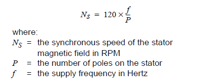
Velocità di un Motore a Induzione
Il campo magnetico creato nello statore ruota a una velocità sincrona (NS) e' definito dalla seguente formula:
Il campo magnetico prodotto nel
rotore a causa della tensione indotta è di natura alternata. Per ridurre la
velocità relativa rispetto allo statore, il rotore inizia a girare nella stessa
direzione del flusso dello statore e cerca di raggiungere il flusso rotante.
Tuttavia, nella pratica, il rotore non riesce mai a "raggiungere" il
campo dello statore. Il rotore gira più lentamente rispetto alla velocità del
campo dello statore. Questa velocità è chiamata Velocità Base (Nb). La differenza tra NS e Nb è
chiamata scorrimento (slip). Lo scorrimento varia con il carico. Un aumento del
carico causerà un rallentamento del rotore o un aumento dello scorrimento. Una
diminuzione del carico causerà un aumento della velocità del rotore o una
diminuzione dello scorrimento. Lo scorrimento è espresso come percentuale e può
essere determinato con la seguente formula: 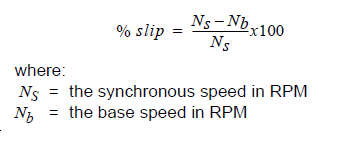
|
|
||
|
|
|||
|
|
|||
|
|
|||