|
INTRODUZIONE
To decode the DCF77 signal, containing the
hourly information, it is necessary to receive the signal on the
77.5kHz frequency. The project presented on this page allows you to
decode the DCF77 signal, obtaining the hourly information, without
purchasing the receiver. All you need is a PC and the card, presented
in this article, which is called BF_DCF77. This circuit allows to
obtain the hourly information present in the DCF77 signal in digital
version, from the audio signal output from the PC tuned to 77.5kHz. via
an SDR radio controllable via web such as the one present at the
following address: SDR WEB RADIO.
The output signal to the board is then connected to the Arduino board
which decodes the digital information obtaining the hourly information.
At the following address DCF_DECODER a project
is presented in which a hardware decoder based on a microcontroller is
created, with an LCD display that uses the BF_DCF77 interface.
THE
INTERFACE BF_DCF77
Figure 1 shows the electric schematic of the
BF_DCF77 interface. The circuit is based on two transistors Q1
and Q2 and a few passive components. This circuit allows to obtain the
envelope of the audio signal present at the IN_BF input giving a
digital version of this envelope on the output pin VOUT.
Fig. 1: electrical diagram of the interface
BF_DCF77
Figure 2 shows the screen capture of the
oscilloscope which shows the waveforms of the audio input signal and
the corresponding digital output.

Fig. 2: CH1 = audio signal input on IN_BF; CH2 output signal
on VOUT
The input stage of the circuit is constituted by
transistor Q1 which is in a class A amplifier configuration. The output
of this stage is therefore applied to the detection stage of the
envelope consisting of D1, C1 and R1 while the stage digitization
consists of Q2, D2 and C3. The circuit works with a voltage of between
3.3V and 5V so it can be directly connected to the Arduino board
IMPLEMENTATION
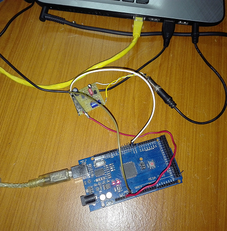
After having created the board, the Arduino board (in this case the
MEGA 2560) is connected to the BF_DCF77 interface. Only three wires are
enough: one for the positive power supply (red) taken from the power
supply connector in the place marked with the abbreviation 5V, one
(black) for the GND and one (green) for the output signal from the
interface that must be connected in the pin 2 of the Arduino board.

SOFTWARE MPLEMENTATION
Here is the code (for Arduino mega2560) which is
a copy of the example in the Arduino DCF77 library. Anyone who wants
can download it directly from the IDE program.
#include <Time.h>
#include <TimeLib.h>


#include "DCF77.h"
#include "Time.h"


#define DCF_PIN 2           // Connection pin to DCF 77 device
#define DCF_INTERRUPT 0    // Interrupt number associated with pin

time_t time;
DCF77 DCF = DCF77(DCF_PIN, DCF_INTERRUPT);

void setup() {
  Serial.begin(9600);
  DCF.Start();
  Serial.println("Waiting for DCF77 time ... ");
  Serial.println("It will take at least 2 minutes until a first update can be processed.");
}

void loop() {
  delay(1000);
  time_t DCFtime = DCF.getTime(); // Check if new DCF77 time is available
  if (DCFtime != 0)
  {
    Serial.println("Time is updated");
    setTime(DCFtime);

  }
  digitalClockDisplay();
}

void digitalClockDisplay() {
  // digital clock display of the time
  Serial.print(hour());
  printDigits(minute());
  printDigits(second());
  Serial.print(" ");
  Serial.print(day());
  Serial.print(" ");
  Serial.print(month());
  Serial.print(" ");
  Serial.print(year());
  Serial.println();
}

void printDigits(int digits) {
  // utility function for digital clock display: prints preceding colon and leading 0
  Serial.print(":");
  if (digits < 10)
    Serial.print('0');
  Serial.print(digits);
}
VIDEO /FOTO
|
